Peak Detector Circuit Using Op Amp
Hello, friends.
In this new blog post, we will see a peak detector circuit using op-amp.
So first, we should see --- What is a peak detector?
The peak detector circuits are used to determine the peak (maximum) value of an input signal. The peak detector circuit utilizes its property of following the highest value of an input signal and storing it. It holds the peak value of input voltages for an infinite time duration until it comes to reset conditions.
Working principle ----->
The working principle of the circuit is such that the peak of the input waveform is followed and stored in terms of voltage in the capacitor.
By the time on moves further, if the circuit detects a higher peak, the new peak value is stored in the capacitor until it is discharged.
The capacitor employed in the circuit is charged through the diode by the applied input signal. The small voltage drop across the diode is ignored, and the capacitor is set up to the highest peak of the applied input signal.
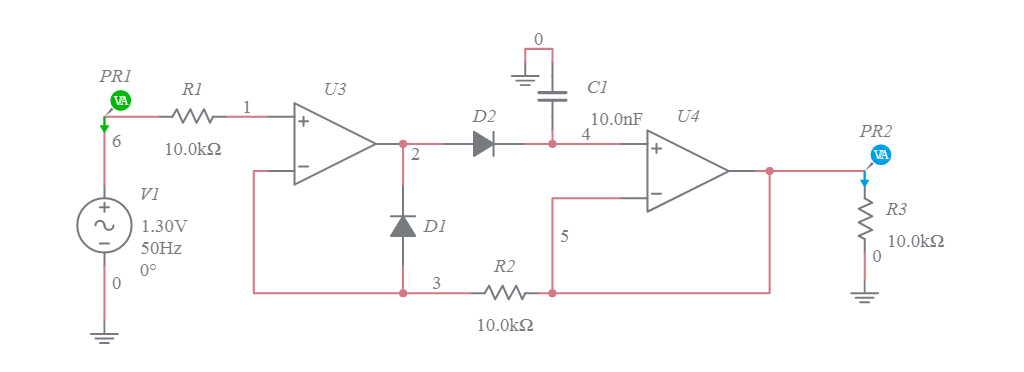
Multisim Live: Peak Detector